Building the VR Tracker
Step 1: Gather the parts
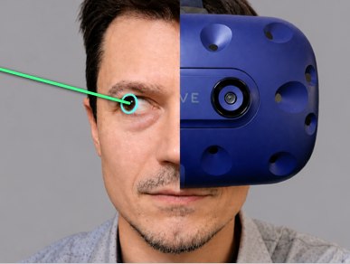
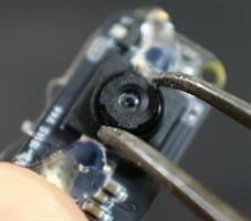
You need a VR or AR headset, a small
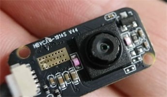
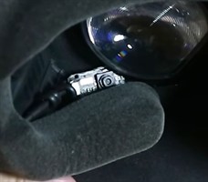
GC0308 eye tracking camera (Fig. 1),
USB extension cables if you
need more cable length, and
soft wire cabling or another
flexible mounting material. This build uses an
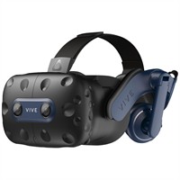
HTC Vive Pro headset (Fig. 2), but the
same idea can be adapted to other headsets. An
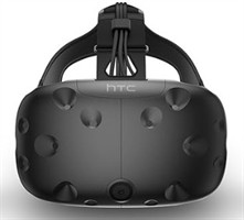
older Vive kit (Fig. 3) can also work if
you already have compatible trackers or controllers.
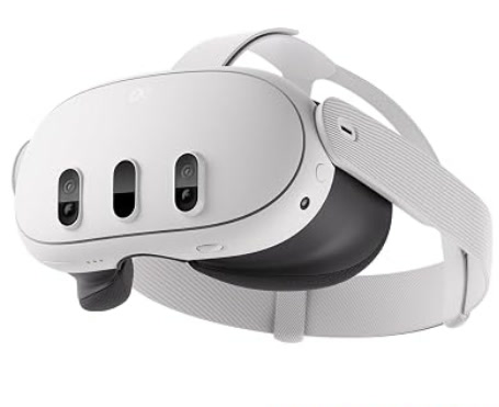
A Quest 3 headset (Fig. 4)
is another example of a headset that can be adapted.
Review IR safety and evaluate the camera's
infrared output before mounting it close to the eye.
The important requirement is that the camera can sit near one eye
without blocking the display or being fully enclosed. The GC0308 can
get warm during use, so leave it exposed enough for heat to escape.
For Stereo Tracking Setup: Use two eye-tracking
cameras, one for each eye, and provide a separate USB connection for
each camera. Both cameras should meet the same focus, heat, and
infrared-safety requirements described above. If the computer does
not provide enough ports near the headset, plan for two extension
cables or a suitable powered USB hub.
Step 2: Set the camera focus
Before mounting the camera,
slightly unscrew the camera lens (Fig. 5) so the
focal distance is roughly 3 centimeters. This puts the eye in focus
when the camera is mounted close to the face inside the headset.
Connect the camera
to your computer and check the stream in any basic
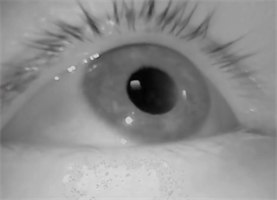
camera viewer. If the image is blurry at eye distance, keep making
small lens adjustments until the pupil and eyelids are clearly visible
(Fig. 6).
For Stereo Tracking Setup: Adjust and test each
camera independently at the distance it will sit from its
corresponding eye. Match the sharpness of the two views as closely as
possible, and confirm that both pupils and eyelids remain visible
before installing the cameras in the headset.
Step 3: Mount the camera inside the headset
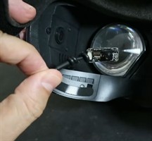
Remove the portion of the display padding on the side where you want
to place the camera (Fig. 7). Use soft wire
to hold the camera
near the lens area,
then bend the wire until the camera has a clear view of your eye.
The exact position and orientation will vary by headset, so treat the
first mount as adjustable rather than permanent.
To verify the view while wearing the headset, open the desktop view
in SteamVR and display the camera feed with a camera viewer (Fig. 8). Adjust
the wire until the full eye is visible and the camera does not block
the headset display.
For Stereo Tracking Setup: Remove or reposition
padding on both sides and mount one camera near each headset lens.
Route and secure both cables so they do not pull the cameras out of
alignment. Verify that the left camera has an unobstructed view of the
left eye and the right camera has an unobstructed view of the right
eye, while neither camera blocks the display.
Step 4: Download the tracker code
Download the Python eye tracking script
and the Unity VR calibration
project from GitHub. The Python script detects the pupil and writes a
gaze vector to a text file. The Unity script reads that file, shows
the uncalibrated gaze point, and guides the headset calibration.
git clone https://github.com/JEOresearch/EyeTracker.git
The main Python script is
3DTracker/Orlosky3DEyeTracker.py.
The Unity files are in
VREyeTracker.
For Stereo Tracking Setup: Use
Orlosky3DEyeTrackerStereo.py instead of the single-camera
Python tracker and use EyeTrackerStereo.cs for the Unity
component. Keep the two stereo files together with the rest of the
downloaded tracker project so their supporting modules and
dependencies remain available.
If you found this software/tutorial useful, please consider
subscribing or
joining
my YouTube channel to support this project!
Step 5: Prepare the Unity scene
In Unity, import the VR rig or SDK for your headset. For a Vive Pro,
the SteamVR assets can be used. Add the downloaded
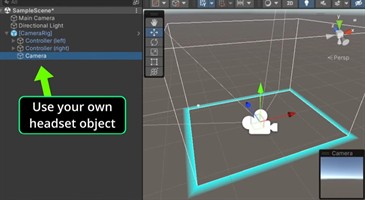
EyeTracker.cs script to the headset object in your scene
(Fig. 9).
This should be the object that represents the headset transform,
because the gaze sphere is positioned relative to the headset in 3D
space.
Set the GazeFilePath value in the Unity script to match
the write path used by the Python tracker. The example script reads
C:\users\jason\gaze_vector.txt, but you should change
that path if your Python script writes gaze_vector.txt
somewhere else. The Unity script expects six values: the three origin
coordinates followed by the three direction coordinates.
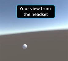
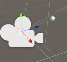
The initial uncalibrated gaze marker is shown in Fig. 10.
For Stereo Tracking Setup: Add
the EyeTrackerStereo.cs script to the headset
object instead of EyeTracker.cs. Then change its
GazeFilePath constant to the exact
gaze_vector.txt produced by the stereo Python script.
This version expects 12 comma-separated values: origin and direction
for the left eye, followed by origin and direction for the right eye.
The script creates separate cyan and magenta eye markers and, after
calibration, a white combined gaze marker. The default eye-origin
offset is 0.032 meters to either side of the headset center; adjust
EyeOriginHorizontalOffset in the script if your headset
or application requires a different value.
Step 6: Run the Python tracker first
Start the Python script before pressing play in Unity. Select the
eye-tracking camera, then let the tracker self-center on your eye.
If the camera image is mirrored or upside down for your headset
mounting position, use the CVflip function in the Python
script to flip the camera image as needed.
python Orlosky3DEyeTracker.py
Once the pupil is being tracked and gaze_vector.txt is
updating, return to Unity and press play. In the Unity scene view,
you should see a moving gray sphere that represents the uncalibrated
gaze estimate.
For Stereo Tracking Setup: Run
python Orlosky3DEyeTrackerStereo.py. In the input window,
choose the correct camera index under Left Eye Camera
and Right Eye Camera, then start both cameras. Do not
assign the same physical camera to both eyes. Use each eye's
flip image checkbox if its mounted view is inverted.
Wait until both eye models are stable and confirm that
gaze_vector.txt is updating with 12 values before
starting Unity.
Step 7: Calibrate the gaze ray in Unity
With the Unity game window selected, press c to begin
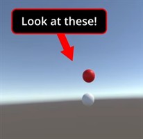
calibration. The script shows three red calibration spheres (Fig. 11): center,
up, and down. Look directly at the center sphere and press
c, then look at the up sphere and press c,
then look at the down sphere and press c. The default
up and down targets are 10 degrees above and below center.
After calibration, the gray sphere should track with your eye. The
script uses the center target to rotate the raw Python direction
forward, then uses the up and down targets to scale vertical gaze
motion. Press b if you want to leave a frozen copy of the
current gaze sphere in the scene for debugging.
For Stereo Tracking Setup: Keep both eyes open and
look at each target with both eyes. Press c once to show
the first target, then follow the five-point sequence shown by
EyeTrackerStereo.cs: up, right, down, left, and center.
Press c while looking directly at each target to record
both eyes at the same time. When all five samples are accepted, the
cyan and magenta eye markers become translucent and the white
combined gaze marker appears. Press g to show or hide
the optional 5-by-5 accuracy grid; with the grid visible, press
t at each highlighted target to record an accuracy test
(Fig. 12).
Step 8: Use the gaze ray in your own project
The calibrated gaze ray (Fig. 13) can be used for gaze analysis, VR interface
selection, attention-aware games, assistive communication, or custom
interaction experiments. In Unity, use the headset origin and the
direction from the headset to the gray gaze sphere as a ray, then
test what it intersects in your scene.
Vector3 gazeDirection = (gazeSphere.transform.position - transform.position).normalized;
Ray gazeRay = new Ray(transform.position, gazeDirection);
For a first prototype, start by drawing the ray and logging the object
it hits. After the ray is stable, add smoothing, dwell selection, or
application-specific behavior.
For Stereo Tracking Setup: Use the white combined
gaze sphere as the binocular target point after calibration. Build
the application ray from the headset transform toward that sphere.
Keep the individual cyan and magenta eye markers available when you
need to inspect disagreement between the eyes or develop
eye-specific interactions.
Step 9: Use AI to build a VR gaze application
You can use an AI coding assistant or large language model to turn
the calibrated gaze ray into a custom VR interaction. Give the model
the Python tracker, the Unity script, and a short description of what
the gaze ray represents. Ask for small testable changes, then paste
any Unity console errors or unexpected behavior back into the chat.
These sample prompts can help you get started:
I have a Unity VR eye tracker that reads gaze_vector.txt from a Python script
and calibrates it into a 3D gaze ray from the headset. Explain how I can use
this ray to select objects in a VR scene.
Modify my Unity script so the gaze ray performs a Physics.Raycast every frame
and highlights the object the user is looking at. Keep the first version simple.
Add dwell selection to this VR gaze tracker. If the user looks at the same
interactable object for 1 second, trigger that object's selection event.
Help me smooth this VR gaze ray without adding too much latency. Explain where
to add the smoothing code in the Unity script.
Here is the Unity console error I get when reading gaze_vector.txt. Explain what
is probably wrong and give me the smallest setup or code change to try first.